

rock band “Jaguar” guitar
The last guitars that were in production are the "Fender Jaguar" guitar from PDP. It's actually a fairly well-made controller and features a folding neck which makes it easy to store.
Unfortunately it still has the same 'mushy' stummer that plagues the older guitars, and the internal layout of the guitar was changed slightly making it a little more difficult to replace the stock strummer with a Strum Fix Plus 2 or Strum Fix Plus 3. If you do wish to install the Strum Fix Plus in one of these guitars, be sure to order the "Jaguar adapter" which includes:
a set of wires for connecting to the strum switch on the motherboard
a little retaining bracket that is used to hold the ribbon cable in place while folding the guitar.
If you have any questions please contact me at guitar@bytearts.com
The first few steps are the same as the other guitars, so you may want to take a look at the standard Strum Fix Plus Installation Instructions but I'll cover those steps here as well.
Required Tools
Phillips screwdriver (No. 1 size works best) - to take guitar body apart.
Small flat-blade screwdriver - for tightening the Strum Fix wire screw terminals.
OPTIONAL: Soldering iron and solder to attach wires to motherboard. The wires can be attached without soldering — see below for the procedure.
Step 1. Take the guitar body apart.
Remove all the screws on the backside of the guitar body. Don't forget about the screw that is underneath the battery cover -- it's a sneaky little b*^%!

Be sure to take off the battery cover to remove the screw in the battery compartment
Flip the guitar over and remove the pick guard -- it's held on with tabs all the way around its perimeter, so you may have to use something thin and flat (a butter knife works well) to reach under the guard and push on the tabs to get them to release. Once it's off, your guitar should like this:

pick guard is off!
Now remove all the exposed screws and you should be able to separate the two halves of the guitar -- watch out that you don't lose the silver barrels the guitar shoulder strap connects to (I like to keep the strap connected to prevent losing the strap connectors). Also be careful of the wires that go from the battery compartment on the back half of the guitar to the motherboard -- you can disconnect them at the motherboard connector, just be careful that you pull on the connector, NOT the wires.
Step 2. Remove the old strummer.
The strummer has a number of screws holding it in place - remove them all (circled in red below) - keep track of them since you'll need some of them later:

Remove these screws - hang on to them, you need some of them later!
Next we need to disconnect the the black and silver ribbon cable that goes from the motherboard to the neck of the guitar. To detach the ribbon cable, first slide the black locking bar that is part of the white connector on the motherboard (see photo below) -- you just need to move it about 1mm to unlock the connector. Once you slide the lock a little bit, you should be able to gently pull on the ribbon cable to disconnect it.

Slide the black locking bar just a bit to 'unlock' the connector and detach the ribbon cable.
Now remove the spring that is attached to the ribbon cable "folder bracket" (the weird, Y-shaped piece of beige plastic). Don’t loose the spring — you will need it later. I find it helpful to tape the bracket to the neck to keep it out of the way.
Now you can remove the small screw that holds the ribbon cable in place (see photo below). Keep track of this screw -- there's only one and it's different than all the others.

remove the screw from the circled location
YOU ARE ABOUT TO VIOLATE ANY WARRANTY ON THE GUITAR, SO PROCEED AT YOUR OWN RISK!
Now we need to cut the wire that goes to the switch on the strummer assembly (this is the DOWN strum switch that registers when you strum down).

cut the wire that goes to the switch on the strummer assembly
The old strummer assembly can now be removed from the guitar by lifting the assembly up out of the guitar and feeding the ribbon cable back through the slots in the bracket.

The old mushy strummer is gone!
Step 3. Connect wires to the strum switch on the motherboard.
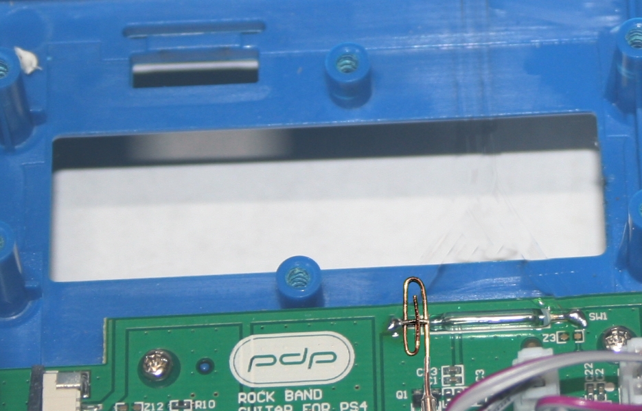
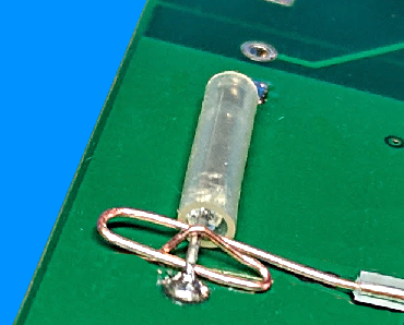
There are two magnetic reed switches on these guitars -- one is the DOWN strum switch that is part of the strummer assembly that we just removed (after cutting the wires to that switch), the other (the UP strum switch) is mounted near the edge of the motherboard near where the strummer was:

This is the UP strum switch on the motherboard - we'll need to attach wires to it
You have to connect 2 wires, each about 4 inches long or so - one to each side of the switch on the motherboard. If you ordered the Strum Fix Plus with the "Jaguar option", then a set of wires for this is included. The preferred way to connect the wires to the is by soldering them to the leads on the switch, but you can also connect them by using the “solderless” method that is described further below.
SOLDER METHOD
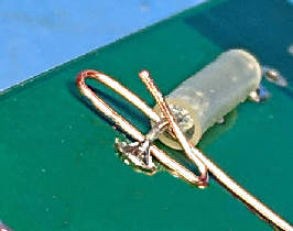
If you have a soldering iron and are comfortable soldering wires, then simply solder wires to the leads of switch on the motherboard as shown in the picture below. Apply a blob of solder to each of the switch leads and then solder the wires in place and trim any excess off the ends of the wires so they look like those shown in the picture.

SOLDER METHOD: Wires soldered to the strum switch on the motherboard
SOLDERLESS METHOD
If you don’t have the necessary tools or inclination to solder the wires to the motherboard, you can use the following “solderless” procedure to connect the wires.
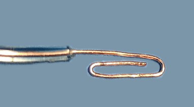
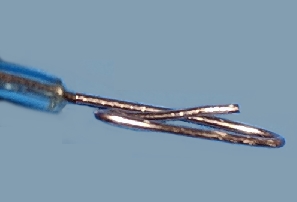
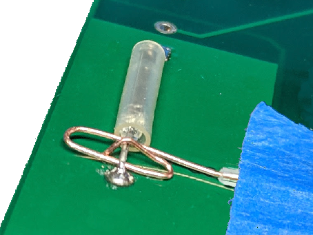
The easiest method is to just feed the wires under the leads of the switch on the motherboard, then fold them back on themselves and twist them together to tighten the connection (like the wire closure on a loaf of bread). This method usually works, but the connection can be flaky. A more reliable method is to form the ends of the wires into a “paperclip” shape and insert them under the leads of the switch on the motherboard, as shown in the photos below. Do each wire one at time, and secure them in place with some tape (or better yet, some hot-melt glue or silicone adhesive).
Step 4. Prepare the loose ends of the wires.
Next you need to prepare the other ends of both sets of wires — the wires you just connected to the motherboard, and the other 2 wires that went to the old strummer assembly that you already cut. The ends of the wires need to be stripped of insulation — if you don't have wire strippers, you can use a knife to lightly score the insulation and then pull it off the ends of the wire with your fingers. You just need to expose about 1/4" of wire:

Strip ends of wires about 1/4" (5mm)

wires stripped, ready for the Strum Fix
Step 5. Secure metal plate.
Next to the hole in the guitar where the strummer was is a metal plate. This plate was held in place by the bracket you removed previously and so needs to be secured in place or else it will rattle around. Use some tape or glue (hot melt glue works great) to secure the plate in place, OR you can place a piece of foam or cardboard on top of the metal plate such that it’s held in place once you’ve assembled everything.
Step 6. Install replacement strummer bracket.
Included with the “Jaguar Option” for the Strum Fix Plus is a small replacement strummer bracket. The main purpose of this bracket is to keep the ribbon cable in place when folding the guitar. Simply install the replacement bracket in the same location as the original.
Place the replacement bracket into the guitar and feed the ribbon cable through it as shown below - be sure to line up the holes in the ribbon cable with the little "posts" and the hole for the screw. Use the small screw (you did save it, right?) to secure the bracket piece in place. Make sure the little round, beige plastic 'axle' piece is in place as shown.

Bracket piece and ribbon cable back in place
Step 7. Connect wires, install the new strummer.
Next you need to reconnect the ribbon cable to the motherboard. Just reverse the process you used when disconnecting the ribbon cable: 1) slide the black locking bar a bit to left, then 2) insert the ribbon cable into the connector (it only goes in about 1-2mm), and 3) slide the locking bar to right to lock the connection.
Next, place the Strum Fix Plus into the guitar, lining up the holes in the corners of the circuit board with the molded-in 'standoffs' of the guitar body. Put 4 of the screws from the old strummer assembly into the holes on the circuit board and gently tighten them down -- DO NOT OVERTIGHTEN OR YOU WILL STRIP THE PLASTIC. (If you do, try using a bit of plastic glue or super glue to hold the screws in place).
Insert the stripped ends of the wires into the screw terminals on the Strum Fix circuit board and gently tighten them -- DO NOT OVERTIGHTEN or you might break the ends of the wires. Gently pull on the wires to make sure they are securely attached to the Strum Fix board.
Put the Y-shaped bracket in place as shown below and connect the spring from the bracket to the small post on the replacement retaining bracket as shown in the photo below. Make sure the little beige colored "axle" piece is also in place as shown - be careful that it doesn't fall out of place when handling the guitar during the next steps.
When everything is done, it should look like the picture below.

behold, the new strummer in all its awesomeness!
Step 8. Reassemble the guitar body.
Now just reverse the first two steps and reassemble the two halves of the guitar. I recommend only putting in a few of the screws on each side at first, just in case you have to take it apart again to check for a loose wire or other issue. Don't forget to reconnect the wires to the battery compartment!
Once you are satisfied everything is working, install the rest of the screws. Be careful to not over-tighten any of the screws or you may strip the plastic.
Thank you for purchasing the Strum Fix Plus, and happy strumming!
